Sonex owners are often pretty smug about how robust our aircraft are, and they are pretty strong, but they are not indestructible. The Sonex was designed as a simple, light, easy to fly aircraft with good performance. Quite a few builders have made changes that John Monnett never intended and obviously disapproves. Quite a few builders are prepared to put up with the consequences of fitting heavier engines and higher gross weights but I want to show that those consequences are real and probably a bit unpredictable. I was pretty sanguine about the Sonex strength, especially after mine survived a high accidental overload (6.9 g, see Sonex Strength) but recently I was lying underneath the fuselage while I cleaned a mix of dirt and oil from the underside when I noticed a couple of dents protruding at least 3 mm from the floor. They had obviously been caused by the inner ends of the wing main spars bending so much that they had pushed out the floor panel where the spars cross over. I was worried enough to remove the wings so I could inspect the inner spars. The other thing I did was to draw a Solidworks model of the inner spar so I could see how it behaved under load. This was only partially successful but it did yield some useful information.
Wing load at 1g
Load on the inner spar – the 1g case at MAUW 522kg (1150 pounds)
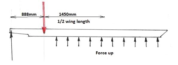
Mass supported by the wing = Half the all up weight – mass of outer part of wing (because it’s the part that is applying the load)
= 522/2 – 25 (my guess at outer wing mass) = 236 kg
Aerodynamic force (force acting upwards on outer wing) F = mg
F = 236 x 9.8 = 2313 N
I have made the assumption that the force is distributed evenly on the wing. This is not necessarily correct and is probably on the severe side, but since the centre of pressure moves around with different manoeuvres it’s probably the simplest guess. The force we need to evaluate the model is the reaction force at the left end of the spar:
Fr = 2313 x 1450/888 = 3777 N
Spar deflection at 6.9g (my big bump case)
We can apply this force to the left end of inner beam to show the stresses in the beam for the 1g case. For higher loads it’s just a matter of multiplying the stress by the g number, but first, let’s have a look at the 6.9g deflection with a force of 6.9 x 3777 = 26061N:
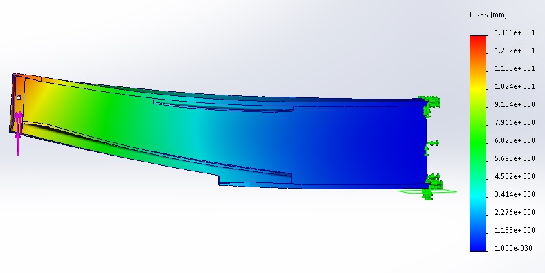
You can see from the model that the deflection of the loaded end compared with the fixed end is 14mm and the deflection at the middle is about 3mm. If we drew a straight line between each end of the inner spar, then the deflection at the middle relative to that line would = 14/2 – 3 = 4mm. This at least means that the model fits pretty closely with the spar deflection which caused the bumps on the underside of my Sonex.
Maximum Stress at 1g
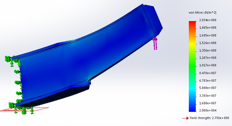
It would appear from the picture that maximum stress at 1g is 203 MPa (MegaPascals) which is very high indeed but if we zoom in to look at the cut-out radius on the bottom of the spar you can see that there is a problem with my model.
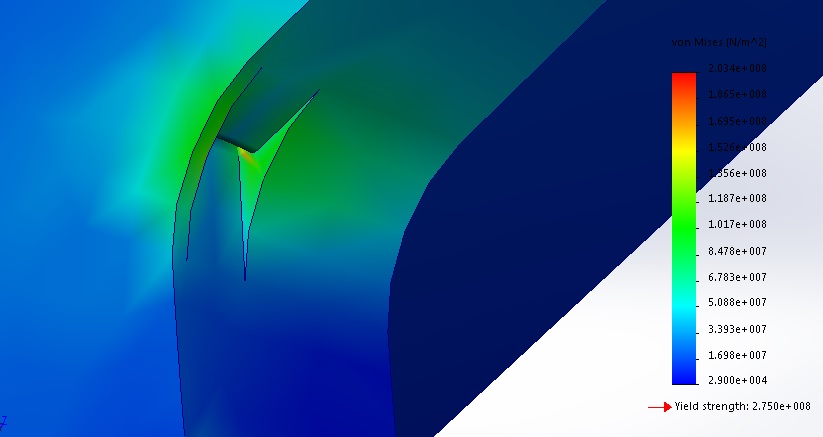
The really high stress indicated is that little tiny yellow area inside the notch. I drew the spar as a one piece structure and that high stress is produced by sharp corners which don’t really exist. However just nearby is the cut-out radius which is coloured green indicating a stress of around 100 MPa, and I think this is probably a pretty good indication of the real stress at this radius under a 1g load. Yield strength of Al 6061-T6 is 275 MPa. From this model, if the load goes above 2.75g (from 275/100) then the material in the radius is going to start yielding or plastically deforming. The wing isn’t going to break of course because the region is so small but it will initiate fatigue cracking. There is no way we can estimate the fatigue life of a Sonex because it depends on how the aircraft is flown and loaded. Even for military and commercial aircraft this is an enormously complex subject, but I think it’s worth looking at a couple of illustrative graphs on fatigue.
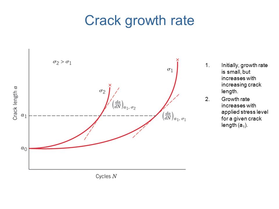
The first graph shows how the rate at which a crack grows changes over the life of a part. It takes a long time for the crack to initiate and grow to a detectable size. As the crack grows, the speed at which it grows increases. Scientists have developed mathematical ways of predicting crack growth, but the really hard bit to predict is the initiation phase. Note that sharp corners are great places to get cracks started.
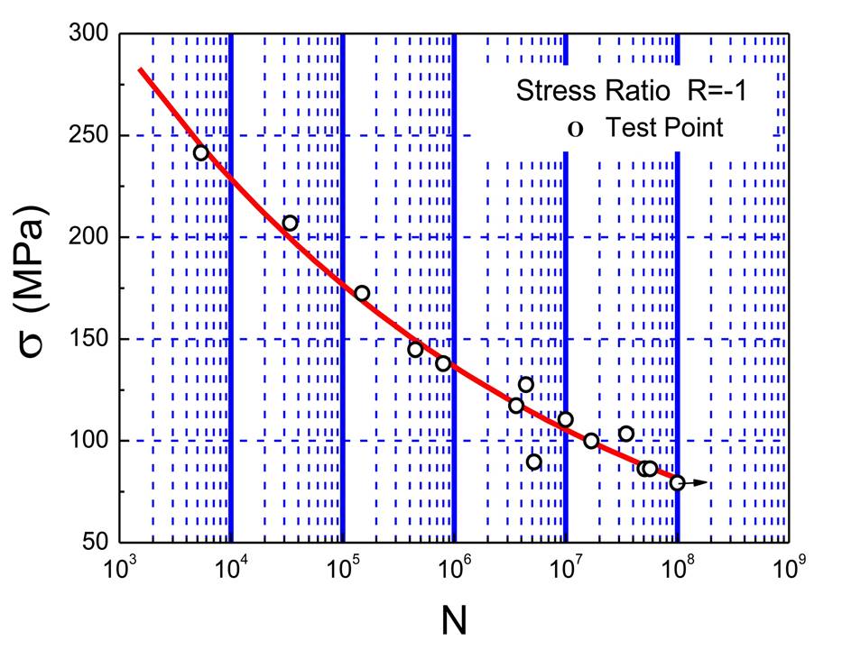
The second graph is an S-N curve, showing Stress against the number of cycles to failure. This looks logical; higher stress means shorter life. Note that the bottom scale is a log scale. The other thing you might notice is that a fairly small increase in stress can cause a disproportionate decrease in life. In fact, just a 10% increase in stress results in the part lasting less than half as long, which finally gets me to the point I would like to make. If you increase the MAUW of your Sonex from 1150 pounds to 1250 pounds, an increase of just 8.7%, you are actually increasing all the loads by 9.6% (the wings don’t count as part of the load remember?) which is enough to halve the fatigue life of the aircraft. I don’t want to alarm people. I happily fly my Sonex and know it is much stronger than my previous aircraft. I don’t have any way of predicting its fatigue life and I’m pretty sure that the Sonex team don’t either because it depends on so many variables, but I am sure that increasing the loading on any aircraft will shorten its fatigue life.
